What Are Robotic Welding Systems and How Do They Work?

Robotic welding systems combine a programmable robot, welding power source, torch, fixture, and control software. Together, these components create repeatable welds on prepared metal parts. The robot follows programmed coordinates and moves the torch along a planned joint. Meanwhile, the power source controls current, voltage, and arc behavior.

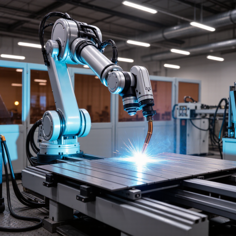
The process begins with accurate part positioning. A fixture holds each component firmly, while sensors or vision equipment can check its location. The controller then activates the arc and guides the torch at a selected speed. Gas shields the molten weld pool from contamination. In a factory, operators may watch the cell through a guarded window, reviewing alarms and weld data from a control panel.

Precision matters.

However, automation is not effortless. A small gap, warped plate, dirty nozzle, or incorrect fixture can produce weak or uneven results. Skilled technicians still inspect samples, adjust programs, replace worn contact tips, and maintain safety systems. Robotic welding systems improve consistency, but they cannot correct every design or material problem independently. That limitation deserves attention. A reliable installation depends on sound engineering, validated procedures, trained personnel, and regular quality checks. Standards, risk assessments, and documented maintenance also support responsible operation. This article explains the main components, working sequence, advantages, and practical limitations of robotic welding systems, helping readers understand where automation performs strongly and where human judgment remains essential.
What Are Robotic Welding Systems and How Do They Work?

What Are Robotic Welding Systems?

Robotic welding systems are integrated production cells that join metal parts automatically. They combine a programmable robot, welding power source, torch, fixtures, sensors, and control software. The robot follows planned paths while the torch maintains a controlled arc, wire feed, and shielding gas flow. An operator usually loads parts, checks settings, and monitors the cell rather than guiding every weld.

The fixture matters. It holds each component in the same position, reducing alignment variation. According to the International Federation of Robotics’ World Robotics 2024 report, manufacturers installed 541,302 industrial robots worldwide in 2023. That figure covers every industrial application, not welding alone. Still, it shows how widely automated production has expanded. A robotic cell can repeat speed, angle, and travel distance with impressive consistency. It can also repeat a mistake perfectly.

Sensors may detect joint location, torch distance, or temperature changes. Software then adjusts movement within programmed limits. However, sensor performance depends on lighting, spatter, calibration, and surface condition. American Welding Society guidance emphasizes procedure control, including current, voltage, travel speed, and shielding conditions. Safety standards also require guarded areas, access controls, ventilation, and trained personnel. In practice, the best system is not always the fastest one. A poorly designed fixture, unstable material, or careless maintenance plan can reduce weld quality quickly. Human inspection remains necessary for critical joints, especially when real production conditions differ from testing.

Key Components of a Robotic Welding System

What Are Robotic Welding Systems and How Do They Work?

A robotic welding system combines mechanical, electrical, and safety components around one controlled process. Its central unit is the robot arm, which positions the welding torch along programmed paths. The controller stores motion instructions and coordinates speed, angle, and travel distance. A welding power source creates the arc, while a wire feeder supplies consistent filler metal. Gas lines protect the molten weld pool.

The fixture holds parts firmly and controls their location. Even a small shift can change penetration or create an uneven bead. Sensors may detect joint position, arc conditions, or contact with the workpiece. A safety enclosure, interlocked doors, emergency stops, and fume extraction protect nearby workers. The International Federation of Robotics reported 541,302 industrial robots installed worldwide in 2023, with 4.28 million operating robots recorded globally in its World Robotics 2024 report. Welding systems represent one practical use of this wider automation growth.

Software connects these components. It controls welding parameters, motion sequences, inspection records, and fault responses. Operators still teach points, replace consumables, and verify sample welds. A robotic cell is not automatically precise. Poor fixturing can defeat expensive programming, and dirty contact tips can interrupt production. This part is often underestimated. Real experience shows that maintenance access matters as much as cycle speed. A system that runs quickly but takes hours to repair may reduce actual output. The American Welding Society has also identified a continuing shortage of skilled welding personnel, making reliable automation valuable, though not a complete replacement for human judgment.

How Robotic Welding Systems Work Step by Step

What Are Robotic Welding Systems and How Do They Work?

How Robotic Welding Systems Work Step by Step

A robotic welding system combines a programmable arm, welding torch, power source, fixtures, and safety controls. The process begins when an operator loads the workpiece into a fixed position. Clamps hold the metal steady. A technician then selects a welding program and checks wire speed, voltage, travel speed, and shielding gas flow. The controller stores these settings as a repeatable movement path. This preparation matters because poor alignment can distort every later weld.

During operation, the arm moves the torch toward the programmed start point. An arc sensor confirms the correct position before welding begins. The torch travels along the joint at a controlled angle and speed. Shielding gas protects the molten pool from air contamination. A wire electrode melts into the joint while the robot follows the planned seam. Sensors may detect height or seam changes and adjust the path in real time. If the joint is uneven, the system cannot always compensate. That limitation deserves attention.

After welding, the robot returns to a safe position, and the fixture releases the part. An inspector checks bead width, surface appearance, penetration evidence, and possible spatter. Critical parts may receive additional non-destructive testing. Operators also review cycle data and compare actual results with the approved procedure. A small fixture shift can create repeated defects, even when the program looks correct. Regular cleaning, calibration, and trial welds keep the system reliable. Automation improves consistency, but skilled oversight remains necessary.

How Robotic Welding Systems Work Step by Step

A robotic welding cycle combines part loading, fixturing, sensing, programmed torch movement, arc welding, and inspection. The chart shows a representative 125-second MIG/MAG welding-cell cycle; actual timing varies with part size, weld length, joint design, and automation level.

The robot controller coordinates the fixture, sensors, wire feeder, shielding gas, power source, and torch motion. Welding usually takes the largest share of the cycle, while loading, clamping, repositioning, and inspection complete the automated sequence.

Common Welding Processes Used by Robots

Robotic welding systems combine a programmed arm, welding power source, positioners, sensors, and safety equipment. The robot follows taught paths while controlling torch movement, travel speed, and weld timing. Process selection depends on material, joint design, production volume, and required appearance. A precise program cannot rescue a poorly prepared joint. That point is easy to underestimate.

MIG or MAG welding is widely used for steel and aluminum assemblies. A continuously fed wire creates the arc and fills the joint. Robots manage long welds consistently, especially on frames, brackets, and structural components. Shielding gas protects the molten pool from air contamination. Operators still inspect wire feeding, gas flow, contact tips, and torch alignment. Small changes can produce porosity or uneven penetration. Heat control matters.

Resistance spot welding uses electrodes to clamp and heat overlapping metal sheets. It is common for repeated seams in vehicle panels and appliance housings. The robot positions each electrode accurately, while the controller manages pressure, current, and weld time. TIG welding offers cleaner, more controlled joints, but it usually moves more slowly. It suits thin materials and visible welds where finish matters. Laser welding can create narrow, low-distortion seams, although joint preparation must be extremely accurate. Sensors may track edges, detect gaps, or adjust the path during production. Even so, sensing is not magic. Reflection remains necessary when real parts differ from the original drawing.

What Are Robotic Welding Systems and How Do They Work? - Common Welding Processes Used by Robots

Welding Process How the Process Works Typical Materials Common Robot Applications Typical Operating Range Main Advantages Key Limitations
Gas Metal Arc Welding (GMAW/MIG/MAG) A continuously fed solid wire electrode creates an arc with the workpiece. Shielding gas protects the molten weld pool from atmospheric contamination. Carbon steel, stainless steel, aluminum, and other weldable alloys. Automotive components, metal frames, machinery, brackets, enclosures, and repetitive fillet or butt welds. Approximately 60–500 A; wire diameters commonly range from 0.8–1.6 mm. Actual settings depend on material thickness and joint design. High deposition rate, continuous operation, broad material capability, and good suitability for robotic path control. Requires shielding gas, careful torch positioning, and protection from drafts. Spatter may occur depending on transfer mode and settings.
Gas Tungsten Arc Welding (GTAW/TIG) A non-consumable tungsten electrode produces the arc. Filler metal may be fed separately or omitted for autogenous welding, while shielding gas protects the weld area. Stainless steel, aluminum, nickel alloys, titanium, and thin carbon steel. Precision pipe joints, thin sections, high-quality stainless assemblies, and components requiring a clean weld appearance. Approximately 5–300 A for many industrial applications; the useful range varies significantly with material, polarity, and thickness. Excellent arc control, low spatter, and high-quality welds with precise heat input. Slower than wire-feed processes, sensitive to contamination and torch alignment, and more demanding to program accurately.
Flux-Cored Arc Welding (FCAW) A continuously fed tubular wire contains flux-forming compounds. The process may use external shielding gas or generate shielding from the flux itself. Carbon steel, low-alloy steel, and some stainless steels. Heavy machinery, structural assemblies, construction components, and thicker steel parts. Approximately 100–500 A; wire sizes commonly range from about 1.0–2.4 mm. High deposition rate, good penetration, and improved tolerance of some surface contaminants compared with solid-wire processes. Produces slag that must be removed between passes. Fumes, spatter, and wire-feed control require suitable extraction and maintenance.
Resistance Spot Welding (RSW) Two electrodes apply force and pass a high electric current through overlapping sheets. Resistance heating forms a weld nugget between the sheets. Low-carbon steel, galvanized steel, stainless steel, and some coated sheet metals. Vehicle body panels, appliance housings, sheet-metal cabinets, and high-volume assemblies with lap joints. Welding current commonly ranges from several thousand to more than 20,000 A, with weld times often measured in cycles or fractions of a second. Very fast cycle times, no filler metal or shielding gas, low visible spatter, and strong repeatability on suitable joints. Limited mainly to accessible lap joints and sheet materials. Electrode wear, part fit-up, and cooling requirements affect quality.
Laser Beam Welding (LBW) A focused laser beam creates localized melting and deep, narrow welds. Filler wire may be added when joint gaps or required reinforcement make it necessary. Steels, stainless steels, aluminum alloys, nickel alloys, and selected dissimilar-material combinations. Battery housings, precision assemblies, thin sheet products, sealed components, and high-speed production lines. Common industrial systems range from approximately 1–20 kW, with travel speeds varying widely according to thickness and joint design. High welding speed, narrow heat-affected zone, low distortion, and excellent repeatability when joint fit-up is controlled. Higher equipment cost, strict safety requirements, sensitivity to joint gaps and surface condition, and more complex process monitoring.
Plasma Arc Welding (PAW) An arc is constricted through a small nozzle to produce a high-temperature plasma jet. The process can operate in transferred-arc or keyhole modes. Stainless steel, carbon steel, nickel alloys, titanium, and other conductive metals. Precision components, pipe and tube assemblies, thin-to-medium sections, and applications requiring stable penetration. Approximately 1–300 A for many industrial systems, depending on operating mode, material, and thickness. Stable arc, concentrated heat source, good penetration control, and suitability for mechanized or robotic welding. More complex torch design and setup than standard arc welding. Nozzle condition, gas flow, and alignment strongly affect results.
Robotic System Functions A robotic welding cell combines a programmable multi-axis arm, welding power source, torch or electrode tooling, workholding equipment, sensors, safety systems, and control software. The system can be configured for steel, stainless steel, aluminum, and other materials compatible with the selected welding process. Repeated production, long weld seams, multi-pass welds, hazardous environments, and applications requiring consistent torch speed and position. Typical industrial robots have 6 or more controlled axes. Cycle time, payload, reach, accuracy, and production rate depend on cell design and part geometry. Consistent motion, improved productivity, reduced operator exposure to arc hazards, programmable quality control, and reliable repeatability. Requires accurate fixtures, suitable part presentation, programming, preventive maintenance, and a production volume that justifies system investment.

Note: Operating ranges are representative industrial values rather than fixed specifications. Actual welding parameters must be established through qualified procedures based on material, thickness, joint design, shielding conditions, and applicable standards.

Applications and Benefits of Robotic Welding Systems

Robotic welding systems use programmable arms, welding tools, controllers, and safety equipment to join metal parts. A technician sets the weld path, speed, angle, and heat settings. The robot then repeats these movements with controlled accuracy. Sensors can detect joint positions and adjust the torch during production. The process is repeatable, not effortless.

These systems serve automotive frames, construction equipment, metal furniture, pressure-rated components, and customized fabrication. They perform especially well on long welds or repeated assemblies. In a busy workshop, a robot can maintain steady torch travel while workers handle inspection, loading, and setup. This division reduces exposure to heat, fumes, sparks, and awkward working positions. It also supports stable weld quality when materials and joint designs remain consistent.

Productivity improves because robots can operate for extended cycles with fewer pauses. Consistent movement may reduce defects, rework, and wasted filler metal. However, robotic welding does not repair poor engineering. Fit-up still matters. Warped parts, dirty surfaces, and changing joint gaps can confuse the process. Skilled technicians must program paths, verify parameters, maintain equipment, and inspect finished welds. A carefully planned cell may deliver safer and faster production, but careless automation can repeat the same mistake many times. That risk deserves regular testing and human review.

SERVO-ROBOT Inc
Privacy Overview

This website uses cookies so that we can provide you with the best user experience possible. Cookie information is stored in your browser and performs functions such as recognising you when you return to our website and helping our team to understand which sections of the website you find most interesting and useful.