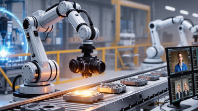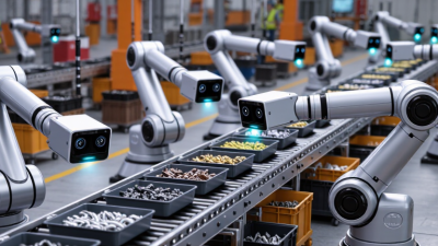
3D robot vision gives machines a practical sense of depth, shape, and position. A robot arm can use that information to find a part in a crowded bin. A mobile platform can spot a floor edge before its wheels reach it. These decisions depend on more than a camera image. They depend on reliable depth data, suitable lighting, and software that can interpret changing scenes.
“ The goal of computer vision is to make useful decisions about real physical objects and scenes based on sensed images,” wrote Berthold K. P. Horn, an authority in computer vision, in Robot Vision. That idea remains useful when comparing the main system types. Stereo vision estimates depth from two viewpoints, much like human binocular vision. Structured-light systems project a known pattern onto an object and measure its distortion. Time-of-flight cameras estimate distance from light’s travel time, while laser triangulation can capture precise profiles on production lines. RGB-D cameras combine color images with depth measurements in one compact unit.
Each approach has trade-offs. A bright factory floor may challenge one sensor, while reflective metal may confuse another. Range, speed, resolution, cost, and calibration all matter. Still, no single ranking works for every task; a tidy “top types” list can hide important limits. The sections ahead compare how these systems work, where they fit, and what engineers should check before choosing one. Depth changes everything. So does context.
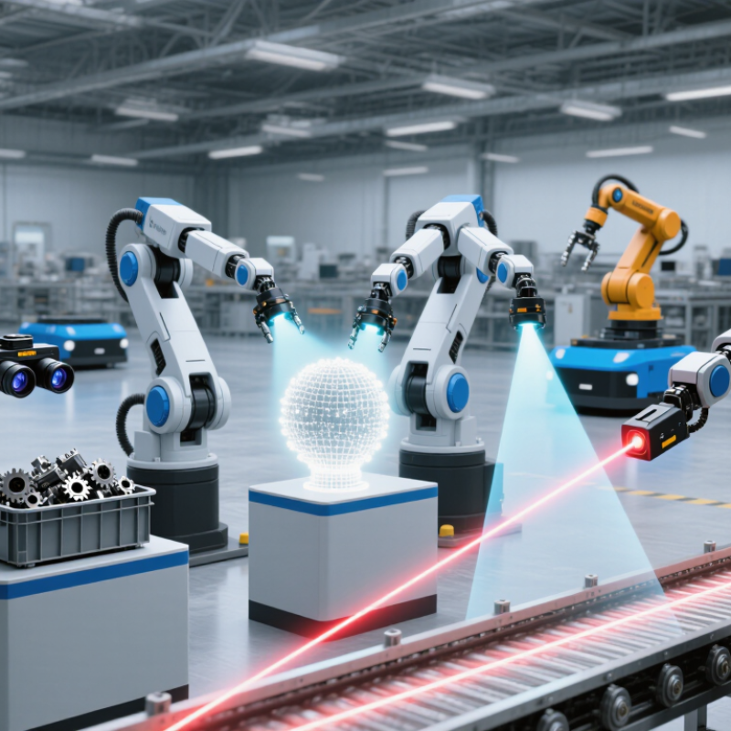
A 3D robot vision system estimates distance, not just shape. Stereo cameras compare two slightly offset images; the shift between matching points reveals depth. Structured-light systems project a known pattern onto an object and measure how it bends across a surface. Time-of-flight sensors estimate distance from returning light, while lidar builds spatial measurements from reflected pulses. Each method produces depth values that can be organized into a point cloud. Calibration then relates those measurements to the camera, robot arm, and workcell coordinates.
The International Federation of Robotics reported 541,302 industrial robot installations worldwide in 2023 in World Robotics 2024. That figure shows the scale of robotic deployment, not how many systems use 3D vision.
In practice, a robot may use depth data to locate a tilted part, avoid a bin wall, or adjust its gripper before contact. Small details matter: shiny metal can scatter projected light, and dark surfaces may return weak signals.
Not always. A clean-looking point cloud can still be wrong if calibration shifts or measurements contain gaps. Operators should test the system with real parts, lighting, and motion speeds—not only ideal sample objects.
Stereo vision uses two cameras to estimate depth from the difference between their images. It works well when objects have visible texture and lighting stays steady. A plain metal panel can be difficult to measure because both cameras may see few matching details. Calibration also matters: even a small camera shift can distort depth estimates.
Structured-light systems project a known pattern onto a surface, then read how that pattern bends. This can reveal shape on objects with limited texture, such as a matte plastic housing. Bright sunlight or reflective finishes may weaken the pattern.
Time-of-flight cameras estimate distance from the time light takes to return. They can capture a broad scene quickly, though edge measurements may blur when nearby surfaces sit at different depths. Fast, but not flawless.
Laser triangulation measures distance from the position of a reflected laser line. It can provide detailed profiles for inspection or controlled pick-and-place tasks, but usually scans a smaller area at a time.
In practice, the choice depends on object speed, working distance, surface finish, and required precision. A robot handling mixed parts may need more than one sensing approach. The trade-offs are easy to underestimate. A clean depth map can still contain gaps, glare, or motion artifacts, so testing with real objects is essential.
What Are the Top Types of 3D Robot Vision Systems?
How Structured-Light Vision Reconstructs Three-Dimensional Scenes
Structured-light vision helps a robot estimate depth by projecting a known pattern onto nearby objects. The pattern may appear as stripes or dots. A camera captures how it shifts across the object’s surface, including edges and curves. Software compares the captured pattern with its original shape and uses triangulation to estimate distance. The output is often a point cloud: a useful map, not a perfect copy of reality. That distinction matters.
In a picking station, for example, projected lines can reveal the height and orientation of a box on a conveyor. Yet shiny, very dark, or partly hidden surfaces can confuse the camera. Ambient light can also reduce pattern contrast. Calibration between the projector and camera is essential, and even a small change in their alignment may affect measurements. Results should be checked under actual working conditions. The setup is not always as tidy as a lab demonstration.
Tips: Keep the projector and camera rigidly mounted, and recalibrate after moving either one. Test with objects that match your real range of colors and materials. If a single view leaves gaps, try another angle. Don’t assume every point cloud is reliable; inspect it for missing edges before a robot acts on it.
| Vision System | How It Measures Depth | Typical Output | Key Strengths | Main Considerations | Common Robot Tasks |
|---|---|---|---|---|---|
| Structured-light vision | A projector casts a known pattern, such as stripes or coded dots, onto a scene. One or more cameras observe how the pattern shifts or deforms. The system matches observed features to the projected pattern and calculates depth using calibrated camera-projector geometry. | A depth map or point cloud, often accompanied by a 2D intensity or color image. | Can capture dense surface detail quickly and does not require the object to move. Pattern design can support reliable correspondence on many textured or low-texture surfaces. | Strong ambient light can reduce pattern contrast. Very dark, reflective, transparent, or highly absorptive surfaces can produce incomplete or unreliable measurements. Projector and camera calibration are important. | Bin picking, object pose estimation, inspection, and measurement of parts within a controlled working area. |
| Stereo vision | Two cameras view the scene from different positions. Depth is estimated from the disparity between corresponding image features; the camera baseline and calibration determine the depth scale. | A disparity map, depth map, or reconstructed point cloud. | Passive stereo can work without projecting a pattern and can provide color images alongside depth. | Matching can be difficult on textureless surfaces, repetitive patterns, or areas with occlusion. Depth uncertainty generally increases with distance and depends on image resolution, baseline, and calibration. | Navigation, obstacle detection, object localization, and scene mapping. |
| Time-of-flight (ToF) | An active sensor emits modulated light and estimates distance from the phase shift or travel time of the returning light. | A per-pixel depth image, often with an intensity image. | Provides direct depth measurements across a field of view and can capture scenes quickly. | Measurements may be affected by multipath reflections, mixed pixels at depth boundaries, ambient infrared light, and the sensor’s operating range and resolution. | Workspace monitoring, obstacle avoidance, human-robot interaction, and coarse object detection. |
| Laser triangulation | A laser line or spot is projected onto an object. A camera observes its position from an offset viewpoint; the angle between the projected light and camera geometry is used to calculate distance. | A profile or depth measurement. Scanning the sensor or object can build a 3D surface model. | Can provide precise measurements of profiles and surface features within a suitable measurement range. | Coverage may require relative motion to build a full surface. Results depend on surface reflectivity, line visibility, sensor geometry, and calibration. | Dimensional inspection, seam tracking, surface profiling, and guided scanning. |
| Monocular 2D vision | A single camera records an image. By itself, a standard 2D image does not directly provide absolute depth; systems may infer scale or pose from known geometry, calibration, multiple views, or other sensors. | A 2D image with detected features, objects, or estimated poses. | Simple imaging setup and useful for color, label, shape, and feature inspection. | Depth and scale can be ambiguous without additional information. Perspective, lighting, and occlusion can affect image-based measurements. | Part presence checks, visual inspection, code reading, and planar pick-and-place. |
Stereo and time-of-flight (ToF) cameras estimate depth in different ways. Stereo systems capture two images from separated viewpoints, then match features such as a bolt edge or floor marking. Depth follows from disparity: nearby objects shift farther between images than distant ones. A wider camera baseline can improve depth sensitivity, but may leave gaps where surfaces look alike or one camera cannot see an object. Calibration matters. A small alignment error can turn a crisp depth map into a misleading one.
The KITTI Vision Benchmark Suite reports stereo results across 194 test image pairs, offering a practical reference for comparing disparity errors (Geiger et al., 2012). ToF cameras instead estimate distance from modulated light’s return phase. The EMVA 1288 standard provides established methods for characterizing image-sensor noise and sensitivity, useful when judging real-world measurement quality. At a 20 MHz modulation frequency, one full phase cycle corresponds to a theoretical unambiguous range of 7.5 meters, using distance = light speed ÷ twice the frequency. Fast, but not foolproof. Dark surfaces, shiny metal, and sunlight can weaken or distort the return signal. Engineers should test the camera on the actual materials, distances, and lighting found on the production line. That step is easy to postpone. It is also where many confident specifications meet less tidy reality.
What Are the Top Types of 3D Robot Vision Systems?
How Robot Vision Systems Differ in Accuracy, Range, and Use Cases
Stereo vision uses two cameras to estimate depth from slightly different images. It suits bin picking and larger work areas, especially when objects have visible texture. Accuracy can fall on plain, shiny, or poorly lit surfaces. Structured-light systems project a pattern onto objects and measure its distortion. They can capture fine detail at close range, making them useful for inspection and precise assembly. Strong ambient light may reduce reliability.
Time-of-flight cameras estimate distance from reflected light and can cover a broad area quickly. They are useful for navigation and obstacle detection, but usually provide less fine detail than close-range systems. Laser triangulation measures depth along a narrow scan line. It can be highly precise for part measurement, though scanning takes time and positioning matters. No single type wins everywhere. A tidy test bench can hide problems that appear beside moving machinery or changing light.
Tips: Match the sensor’s working range to the actual task distance, then test with real parts. Check cycle time, surface finish, lighting, and occlusion. Leave room for calibration drift; it is easy to underestimate.