



How to Use Seam Tracking for Better Welding Results?
How to Use Seam Tracking for Better Welding Results?
A stable weld begins before the arc starts. It begins with a visible, repeatable joint. In real workshops, however, plates shift, gaps vary, and heat pulls the joint sideways. Seam tracking helps the welding torch follow the actual joint instead of the programmed path. That difference can reduce undercut, uneven penetration, and costly rework.
The American Welding Society’s 2023 workforce report estimated that the United States could face a shortage of more than 330,000 welding professionals by 2026. Automation cannot solve every skills gap, but it can support consistency when experienced operators are scarce. The U.S. Bureau of Labor Statistics also projects strong replacement demand for welders, cutters, solderers, and brazers through 2032. These figures make process control more than a productivity goal.
Dr. John C. Lippold, a recognized welding researcher and author, has expressed a practical principle often applied to automated welding: “A weld is only as good as the control of the process behind it.” Seam tracking puts that principle into action. Laser, through-arc, and tactile systems can detect joint movement during welding. Each method has limits. Reflective surfaces can confuse laser sensors. Arc signals may drift with changing parameters. Tactile probes can react too slowly.
The honest lesson is simple. Seam tracking is not magic. It is a feedback system that needs correct calibration, clean joint preparation, and operator judgment. A torch may look perfectly aligned while the root remains poorly fused. Measure the result, inspect the bead, and adjust the process. That discipline creates better welding results.
Understanding Seam Tracking in Welding
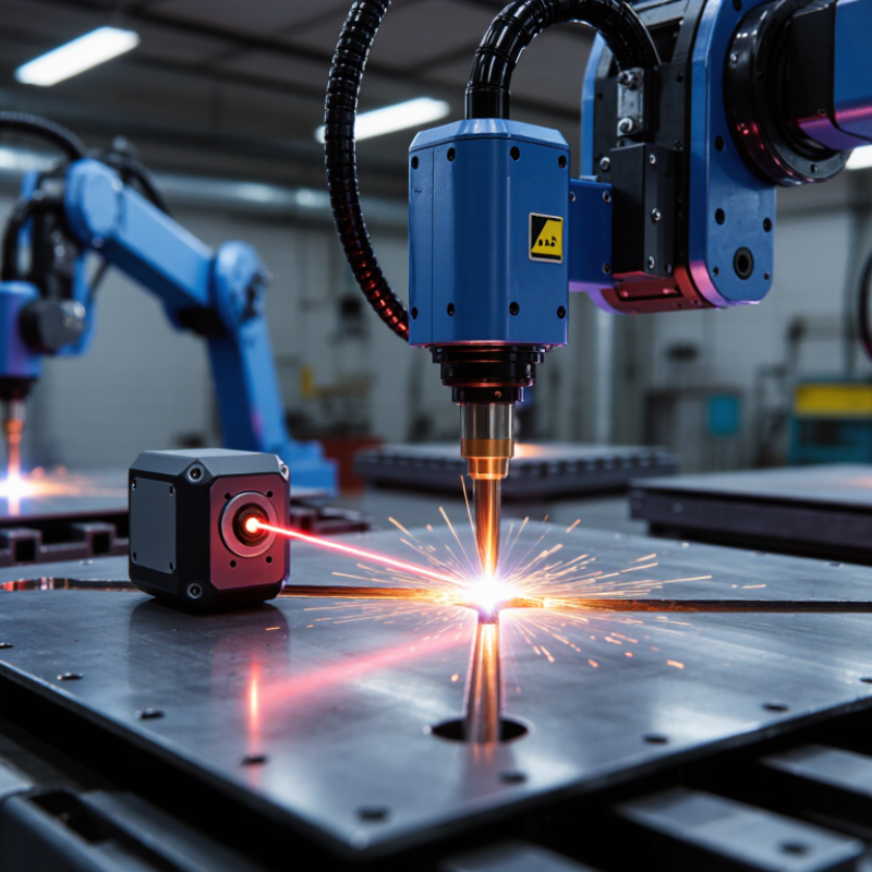
Understanding seam tracking in welding starts with one simple idea: the torch must follow the joint, not an assumed drawing. A sensor detects the seam’s changing position, then sends corrections to the welding controller. Laser vision systems read joint geometry, while through-arc tracking uses changes in arc voltage during controlled weaving. These methods help compensate for plate distortion, inconsistent fit-up, and minor fixture movement. A 2024 report from the International Federation of Robotics recorded 4.28 million industrial robots operating worldwide in 2023. This growth reflects wider confidence in automated positioning, including welding applications.
In practical work, setup still decides much of the result. Clean the sensor window, confirm its stand-off distance, and calibrate over a representative joint. A narrow V-groove may require different search limits than a wide fillet weld. Keep the correction speed moderate. Excessive movement can create a visible waviness in the bead. The American Welding Society has estimated that the United States may need 330,000 new welding professionals by 2026, increasing interest in systems that support skilled operators. Seam tracking does not replace judgment. It can miss a dark scale patch or confuse a nearby edge. I have seen accurate sensors produce poor welds after careless calibration. Record deviation signals, bead width, and travel speed during trials. Those details reveal whether the system is correcting the joint or merely chasing noise.
How to Use Seam Tracking for Better Welding Results? - Understanding Seam Tracking in Welding
Comparison of common seam-tracking approaches and practical setup factors for improving weld placement, consistency, and process control.
| Seam-Tracking Method | Detection Principle | Typical Welding Processes | Contact with Workpiece | Best-Suited Joint Features | Main Advantages | Key Limitations | Important Setup Factors |
|---|---|---|---|---|---|---|---|
| Touch Sensing | The welding wire or a dedicated sensing probe makes electrical contact with the workpiece to locate an edge or reference point before welding. | GMAW FCAW GTAW | Yes; an electrical contact is required during the sensing cycle. | Plate edges, start points, tack-welded assemblies, and simple joint locations. | Low hardware complexity, reliable on clean conductive metal, and useful for pre-weld position finding. | It generally locates the seam before welding rather than continuously correcting the torch path. It is unsuitable for nonconductive surfaces and can be affected by poor electrical contact. | Use a stable work return, clean contact areas, suitable sensing current, and a safe search path that avoids damaging the wire or probe. |
| Through-the-Arc Tracking | The controller analyzes changes in welding current or arc voltage as the torch oscillates across the joint. These changes indicate torch position relative to the seam. | GMAW FCAW SAW | No separate contact sensor is required; the welding arc provides the feedback signal. | V-grooves, fillet joints, butt joints, and seams with enough geometry to produce a measurable left-right signal difference. | Works during welding, requires no optical line of sight, and can tolerate smoke, spatter, and moderate surface contamination better than optical methods. | It depends on a stable arc and controlled torch oscillation. Poor joint definition, changing gap conditions, excessive spatter, or unstable welding parameters can reduce accuracy. | Maintain consistent wire feed speed, arc length, travel speed, oscillation width, dwell time, and left-right current or voltage sampling. |
| Laser Vision Tracking | A laser line or structured light pattern is projected onto the joint, while a camera measures the reflected profile to calculate seam position and geometry. | GMAW GTAW PAW Laser Welding | No; it is a non-contact measurement method. | Butt joints, lap joints, fillets, grooves, changing gaps, and joints requiring height or cross-section measurement. | Provides geometric information before and during welding, supports adaptive correction, and can measure seam position, gap, height, and joint profile. | Optical performance can be affected by arc brightness, smoke, spatter, reflective surfaces, surface scale, and blocked visibility. | Set the sensor angle and stand-off correctly, shield the optics from spatter, use appropriate optical filtering, and calibrate the camera-to-tool center point. |
| Laser-Reflection Tracking | A laser spot or line is reflected from the workpiece, and the sensor detects changes in reflected light to estimate the seam position. | GMAW GTAW Laser Welding | No; the sensor measures reflected light from a distance. | Clearly visible grooves, edges, and joints with sufficient contrast or height variation. | Fast response, compact sensing hardware, and suitability for automated torch correction where a defined seam profile is visible. | Dark, shiny, oxidized, or uneven surfaces may produce inconsistent reflections. Arc light and contamination can also reduce signal quality. | Control sensor stand-off, incidence angle, optical shielding, surface cleanliness, and detection thresholds. |
| Mechanical Roller or Follower | A spring-loaded wheel, stylus, or guide physically follows an edge or groove and transmits the position to the torch or welding carriage. | GMAW FCAW SAW | Yes; the follower remains in physical contact with the workpiece. | Long, continuous edges, formed channels, rails, and joints with a consistent mechanical reference. | Simple, easy to understand, and largely unaffected by arc light, smoke, or optical reflections. | Mechanical wear, friction, surface damage, and inertia can limit tracking performance. It may not follow narrow or discontinuous seams effectively. | Select suitable spring force, follower geometry, travel speed, and contact material. Keep the follower free of spatter and verify that contact pressure does not deform thin material. |
| Inductive or Eddy-Current Sensing | An electromagnetic field detects changes in conductivity, material presence, or distance near the joint without requiring direct electrical contact. | GMAW GTAW Automated Welding | No direct contact is required. | Metallic edges, gaps, lap joints, and applications where optical visibility is limited. | Not dependent on visible light and capable of operating through some smoke or surface contamination. | Performance depends on material properties, sensor distance, joint geometry, and calibration. It is generally less informative than vision systems for full seam-profile measurement. | Calibrate for the specific material and thickness, maintain a controlled stand-off, and account for magnetic or conductive changes caused by nearby parts. |
| Ultrasonic Tracking | Ultrasonic waves are transmitted into or toward the workpiece, and reflected signals are analyzed to identify geometry, thickness changes, or a joint location. | Automated Welding Cladding Specialty Processes | Usually no direct contact when an air-coupled or stand-off arrangement is used; some systems require a couplant or contact path. | Applications requiring subsurface information, thickness measurement, or tracking where optical access is difficult. | Can provide information not available from surface-only optical sensing and is less dependent on visible arc light. | System integration is more complex, and signal quality depends on coupling, material structure, surface condition, and joint geometry. | Control sensor alignment, coupling conditions, signal filtering, material calibration, and the distance between the sensor and torch. |
Related Posts
-

Why Is Seam Tracking Welding Essential for Precision in Modern Manufacturing?
-
10 Essential Tips for Effective Seam Tracking in Robotics
-

Top Robotic Camera System Suppliers Worldwide?
-

Top 10 Robot Servo Tips for Global Buyers to Consider
-

2026 Best Inspection Robot for Efficient Quality Control?
-

Transforming Industry with Intelligent Robots at the 138th Canton Fair in 2025