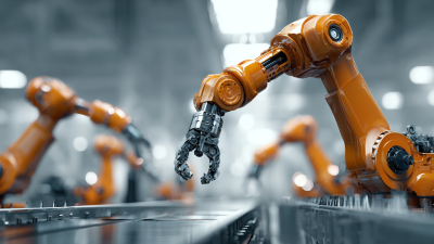
Choosing among 3d vision systems for robots in 2026 requires more than comparing camera resolution or processor speed. Modern factories demand reliable perception around metal reflections, changing light, dust, vibration, and moving workers. A system that performs well in a showroom may struggle beside a fast conveyor.
This guide examines leading solutions through practical buying criteria. These include depth accuracy, scanning range, latency, calibration effort, software compatibility, safety features, and total ownership cost. It also considers integration with robotic arms, programmable logic controllers, and common industrial communication protocols. Real deployment details matter. A camera mounted above a bin must identify partly hidden parts, estimate grasp points, and recover when objects overlap.
Small details decide success.
The guide draws on engineering principles, published manufacturer specifications, and realistic automation scenarios. It separates measured capabilities from marketing claims wherever possible. However, performance can vary with lenses, lighting, robot motion, object materials, and installation quality. That limitation deserves attention. No single vision system fits every application, and even strong products may need custom calibration or better lighting.
Readers will find comparisons designed for informed decisions, not rushed purchases. We highlight systems suitable for bin picking, inspection, palletizing, navigation, and collaborative robotics. We also discuss maintenance, training requirements, data security, and future upgrade paths. By the end, buyers should understand which specifications affect production results, which features add little value, and which questions vendors must answer before installation.
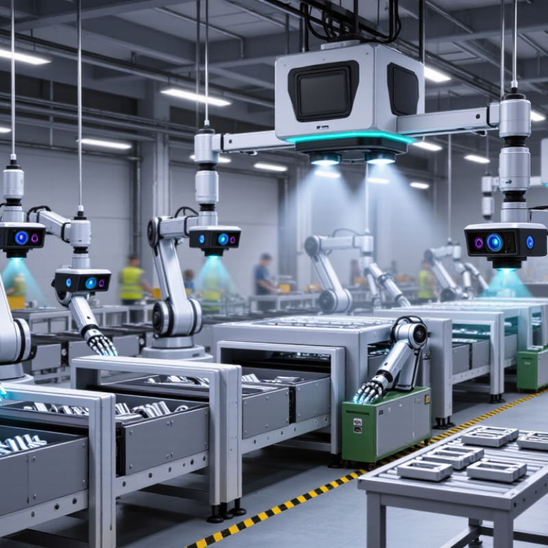
A 3D vision system gives robots depth, shape, and spatial context. A standard camera may see a flat image. A 3D sensor can estimate how far each object sits from the gripper.
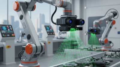
This changes the robot’s decisions. It can locate parts inside a bin, calculate grasping angles, detect surface defects, and avoid nearby equipment. In a packaging cell, the system builds a point cloud from each scene. Software then separates overlapping objects and sends coordinates to the robot controller. The robot does not simply “see” a part. It measures a usable position.
The need is growing. The International Federation of Robotics reported 541,302 industrial robots installed worldwide in 2023, with more than 4.28 million operating robots globally in its World Robotics 2024 report. More robots also mean more variation, speed, and safety demands. A 3D system helps manage these conditions, especially when parts arrive randomly or change between production runs.
Depth data is not magic. Reflective metal, dark plastic, dust, and vibration can reduce accuracy. I have seen promising trials fail because lighting and calibration received too little attention. The first scan is rarely perfect. Buyers should check point-cloud density, latency, working distance, field of view, and integration support. A sensor with impressive laboratory accuracy may perform poorly above a fast conveyor. Real production samples matter more than a polished specification sheet.
Modern robotic 3D vision depends on more than a high-resolution camera. Stereo vision estimates depth from two viewpoints, while structured light projects patterns onto objects. Time-of-flight sensors measure reflected light pulses. LiDAR can support larger workspaces, but surface texture and lighting still affect accuracy.
The International Federation of Robotics reported 541,302 industrial robots installed worldwide in 2023. That growth increases demand for reliable perception during picking, inspection, and bin sorting. Industry analysis from MarketsandMarkets projects strong expansion in the 3D machine vision market through 2028. Yet accuracy claims need careful testing. A sensor may perform well in a laboratory, then lose precision near glossy metal, black plastic, or moving parts. Depth is not enough. Software must also filter noise, identify edges, and estimate object pose. Practical trials should measure cycle time, missed picks, recalibration frequency, and performance under changing factory light.
Tips: Test representative objects, not ideal samples. Record depth errors at different distances. Use calibration targets before production shifts. Keep a backup detection method when surfaces become reflective. Review false positives weekly; small errors can expose weak training data or poor mounting. The best 3D vision system is not always the most expensive one. It is the system that remains understandable, serviceable, and stable after installation.
2026 Best 3D Vision Systems for Robots Buying Guide
Choosing a 3D vision system should begin with the robot’s application, not the camera’s specification sheet. A bin-picking robot may need strong depth accuracy, wide coverage, and reliable object separation. A quality inspection cell may need finer resolution, stable lighting, and repeatable measurements. For palletizing, speed and working distance often matter more than extreme detail. These differences can change the best choice completely.
Test the system with real parts, surfaces, and movement speeds. Shiny metal, black plastic, transparent packaging, and dusty components can produce missing or distorted depth data. Measure detection success, cycle time, calibration stability, and recovery after a failed scan. A system that performs well in a showroom may struggle beside vibration or changing factory lights. I have found that integration effort is often underestimated. That assumption deserves review.
Tips: Compare complete workflows, not isolated sensor numbers. Check mounting space, cable routing, software compatibility, and operator training. Ask for application data from similar objects. Record false detections during repeated trials. Leave room for imperfect parts. Reliable performance matters more than impressive peak accuracy.
Application-focused comparison of common 3D vision system categories. Values are typical engineering ranges and should be verified against the selected system's technical specification, robot accuracy, lighting conditions, and integration requirements.
| Application | Recommended 3D Vision Category | Typical Working Distance | Typical Depth Range | Typical Measurement Accuracy | Typical Capture Speed | Surface and Lighting Suitability | Key Selection Criteria | Main Limitation |
|---|---|---|---|---|---|---|---|---|
| Bin Picking and Random Part Handling | Industrial 3D snapshot camera or structured-light sensor | 0.4–2.0 m | 0.3–2.5 m, depending on field of view | Approximately 0.5–3 mm at the target distance | About 1–15 frames/s | Works well with textured and matte parts; reflective or dark parts may require controlled lighting or surface treatment | Occlusion handling, point-cloud completeness, pose estimation, collision checking, and robot communication | Nested parts, transparent surfaces, and severe occlusion can reduce detection reliability |
| Depalletizing and Case Unloading | Long-range 3D time-of-flight, stereo, or structured-light system | 1.0–4.0 m | 1–5 m | Approximately 2–10 mm | About 5–30 frames/s | Suitable for boxes and cartons; direct sunlight and highly reflective wrapping can affect depth quality | Large field of view, depth stability over pallet height, ambient-light immunity, and fast cycle-time support | Longer working distances normally reduce fine detail and small-feature accuracy |
| Bin Inventory and Warehouse Measurement | Wide-area 3D time-of-flight or stereo camera | 2.0–10.0 m | 2–15 m | Approximately 5–30 mm | About 10–60 frames/s | Best for general geometry and occupancy; very dark, shiny, or transparent items may create missing depth | Coverage area, multi-camera synchronization, data bandwidth, environmental protection, and calibration stability | Not intended for tight-tolerance dimensional inspection |
| Assembly Guidance and Part Localization | High-resolution stereo or structured-light camera | 0.2–1.5 m | 0.1–1.0 m | Approximately 0.1–1 mm | About 5–30 frames/s | Good for textured or geometrically distinctive parts; controlled illumination is usually recommended | Resolution, repeatability, pose accuracy, calibration method, and compatibility with robot hand-eye calibration | Higher resolution can reduce field of view and increase processing requirements |
| Surface Inspection and Dimensional Verification | Calibrated structured-light or laser triangulation system | 0.1–1.0 m | 0.05–0.5 m | Approximately 0.02–0.2 mm in controlled conditions | About 1–100 profiles/s or 1–30 frames/s | Best with stable lighting and controlled reflectivity; glossy, translucent, or highly absorptive surfaces need validation | Calibration traceability, repeatability, point density, measurement uncertainty, and temperature stability | Usually requires tighter mechanical and lighting control than general robot guidance |
| Welding Seam and Bead Tracking | Laser line profiler or rugged 3D triangulation sensor | 0.1–0.8 m | 0.05–0.4 m | Approximately 0.02–0.5 mm | Approximately 100–2,000 profiles/s | Designed for industrial surfaces; welding arc light, smoke, spatter, and hot metal require shielding and filtering | Profile rate, laser filtering, thermal protection, vibration resistance, and real-time robot control | Generally measures a profile or cross-section rather than a complete 3D scene |
| Pallet and Load Dimensioning | Multi-camera stereo or wide-area time-of-flight system | 1.5–8.0 m | 1–10 m | Approximately 5–25 mm | About 5–30 frames/s | Suitable for cartons, bags, and mixed loads; occlusions and gaps between objects must be considered | Coverage, camera overlap, synchronization, edge detection, dust protection, and measurement repeatability | Accuracy decreases when load edges are hidden, irregular, or poorly contrasted |
| Mobile Robot Navigation and Obstacle Detection | Depth camera, stereo camera, or 3D LiDAR | 0.2–30 m, depending on sensor type | 0.2–30 m | Approximately 5–100 mm for general navigation | About 10–30 frames/s or 5–20 scans/s | Depth cameras need suitable texture and exposure; LiDAR is less dependent on visible texture but may have lower fine detail | Range, field of view, outdoor performance, motion tolerance, dust and water protection, and computational load | Navigation-grade sensing is not a substitute for high-accuracy inspection or precise picking |
| Food, Pharmaceutical, and Hygienic Handling | Sealed 3D camera or structured-light system with hygienic mounting | 0.3–2.0 m | 0.2–2.5 m | Approximately 0.5–5 mm | About 5–30 frames/s | Must be validated on wet, glossy, translucent, or irregular products; washdown and contamination control are important | Ingress protection, cleanability, corrosion resistance, food-contact separation, and reliable operation under changing product appearance | Hygienic enclosure requirements can increase system size, cost, and installation complexity |
Choosing a 3D vision system for robots requires more than comparing resolution numbers. Start with the task, part size, surface texture, and robot speed. A sensor must capture reliable depth at the real working distance, not only in laboratory conditions. Measure the smallest feature the robot must locate, such as a 2-millimeter edge or a shallow socket.
Lighting deserves serious attention. Glossy metal, black plastic, dust, and changing shadows can weaken depth data. Test representative parts under factory lighting, including damaged or poorly positioned pieces. Calibration should remain stable after temperature changes and routine maintenance. Integration also matters. Check communication options, trigger timing, processing time, and compatibility with the robot controller. A clear diagnostic interface can reduce troubleshooting hours.
Tips: Request sample scans before purchasing. Compare accuracy, repeatability, cycle time, and false detections. Keep a few difficult parts for acceptance testing. Do not trust a perfect demonstration. Production results are usually less clean. I have seen systems perform well on centered parts but struggle when objects overlap. That weakness should be documented, not hidden. Allow adjustment time for mounting, calibration, and software tuning. A slightly slower system may deliver better uptime when its data remains consistent.
Robot vision is moving from simple depth capture toward adaptive, AI-assisted perception. The International Federation of Robotics reported 541,302 industrial robot installations worldwide in 2023. More robots now work beside people and handle variable objects. That shift increases demand for reliable 3D scene understanding. Edge processing is becoming essential. It reduces latency when a robot sorts parts at high speed. It also limits unnecessary cloud data transfers. McKinsey’s 2024 State of AI survey found that 72% of organizations use AI in at least one business function. Yet, this does not guarantee accurate vision. Training data still matters.
The best 3D vision systems in 2026 will combine depth sensing, synthetic data, and real-time anomaly detection. Time-of-flight and structured-light sensors each have weaknesses. Reflective metal can confuse depth readings. Dark surfaces remain difficult. Calibration is often overlooked. A few millimeters of error can misplace a gripper. Look for systems supporting automatic calibration, edge inference, and transparent performance logs. Cybersecurity also deserves attention, especially when cameras connect to factory networks. The World Economic Forum’s Future of Jobs Report 2025 identifies AI and information processing as major business transformation drivers. However, buying the newest sensor is not always wise. Test it with your actual parts, lighting, dust, and motion. Real factories are rarely clean laboratories. That lesson is easy to forget.
Depth repeatability is a key buying criterion for robotic inspection, bin picking, and precision guidance. The chart shows representative industrial performance ranges by sensing method; lower values indicate finer repeatability. Actual results vary with distance, surface finish, lighting, calibration, and temperature.
Buying insight: Laser triangulation and structured-light systems are generally preferred for high-precision inspection, while stereo and time-of-flight systems are often selected when larger working volumes, flexible outdoor operation, or faster scene coverage are more important.