How to Choose a Seam Tracking System?
Choosing a seam tracking system means matching its sensing method to the weld, joint, and production conditions. That sounds straightforward. In practice, a narrow groove, reflective metal, surface scale, or changing torch angle can affect what a sensor detects. Small details matter. Before comparing models, define the job: material, joint geometry, expected seam variation, travel speed, and mounting access. Then confirm whether the system locates the seam before welding, during welding, or both. These functions are not interchangeable. Camera-based, laser-based, and touch-sensing approaches each suit different conditions; none is automatically best. Ask suppliers for operating limits, calibration steps, and test results from similar parts, not just polished demonstrations.
Integration deserves equal attention. Check compatibility with the robot or welding controller, available mounting space, cable routing, and the time needed to change programs or recalibrate. A capable sensor can still underperform if vibration, spatter, poor lighting, or an awkward bracket disrupts its view. Plan a trial using representative workpieces, including imperfect ones. Record tracking errors, setup time, and how often an operator must intervene. A clean demo can mislead. No system removes every process variation. It may be tempting to select the fastest option, but stable tracking and straightforward recovery can matter more on a real production line. The right choice is the one that meets your required accuracy and speed in your actual environment, with performance you can verify and maintain. Some trade-offs will remain; identifying them early is part of choosing well.
Understanding Seam Tracking Systems and Their Core Functions
How to Choose a Seam Tracking System?
Understanding Seam Tracking Systems and Their Core Functions
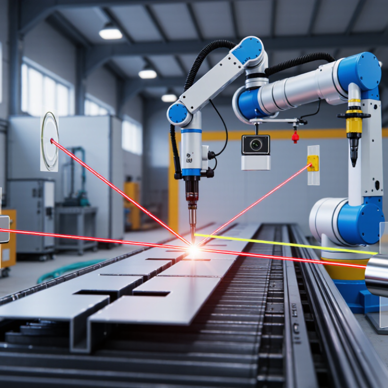
A seam tracking system detects a joint and adjusts the welding path as the workpiece moves or shifts. Its core functions are sensing, locating, and correcting. Sensors may use a camera, laser profile, or contact probe to find the seam. A controller then converts that measurement into a position correction for the torch. The goal is consistent alignment, not simply a clear image. That distinction matters.
Sensor performance depends on the actual joint. A narrow groove, changing gap, or reflective surface can make detection less stable. Welding speed, fixture movement, and spatter may also affect readings. For example, a sensor tested on a clean, stationary coupon may behave differently on a curved part moving through production. Test representative materials and joint geometries where possible. Not always easy.
A useful system should provide repeatable measurements, suitable response speed, and clear fault or signal information. Check how it handles missed seams and sudden path changes, not only ideal conditions. Calibration and mounting stability matter too; even a capable sensor can give poor corrections when its position shifts. One detail is easy to overlook: tracking cannot compensate for every fit-up problem. Review the sensor, controller, torch interface, and process together, then verify performance with real parts.
Identifying Welding Requirements and Operating Conditions
Before choosing a seam tracking system, define the joint and the conditions it must handle. Record material, thickness, weld process, travel speed, seam type, and allowable deviation. A narrow butt joint on clean sheet metal presents different demands from a fillet weld on a warped, scaled component. Measure actual gaps across several parts, not just the drawing. Small details matter.
Check what the sensor will see during production. Arc glare, smoke, spatter, reflective surfaces, vibration, and changing torch angles can disrupt readings. Note the available mounting space and sensor-to-work distance, too. The International Federation of Robotics’ World Robotics 2024 report counted 4.28 million industrial robots operating worldwide in 2023, underscoring how often tracking must work within automated cells. But a growing robot count does not guarantee a stable weld process. Test under realistic conditions.
Match system response and measurement range to the line’s speed and variation. Ask whether tracking must correct lateral offset, height changes, or both, and verify performance on representative parts. The American Welding Society’s workforce outlook projected demand for about 330,000 welding professionals in the United States by 2028. Automation can support production, but it cannot compensate for poorly defined requirements. A clean trial part may mislead. Repeat trials with ordinary parts, including the awkward ones.
Comparing Seam Tracking Technologies and Sensor Types
How to Choose a Seam Tracking System?
Comparing Seam Tracking Technologies and Sensor Types
Laser profile sensors project a line across the joint and measure its shape. They can detect groove position and height before the torch arrives. This works well when parts vary slightly. But shiny metal can create glare, while spatter may obscure the lens. A clean protective window matters.
Vision cameras identify joint edges through image contrast or geometry. They suit visible seams and flexible inspection setups, but changing light, dark coatings, or clutter can confuse detection.
Contact probes take a simpler route: a physical tip follows the seam. They tolerate some dirty conditions, though they add contact, wear, and possible delays.
Arc sensors infer torch position from electrical signals during welding. They often need a weaving motion and a compatible process. Useful, but not universal.
Match the sensor to the joint and production conditions. A narrow butt joint on reflective sheet may need different sensing from a large fillet weld with visible edges. Check response time, mounting space, cleaning access, and calibration effort. Test with real parts, not only a perfect sample. Small surface changes matter. I would not call any option maintenance-free; even a strong sensor can drift or lose a clear view. The best choice is the one that tracks reliably at your actual speed, with operators able to verify its readings.
Evaluating Integration, Accuracy, and Environmental Compatibility
How to Choose a Seam Tracking System?
Evaluating Integration, Accuracy, and Environmental Compatibility
A seam tracker must fit the welding cell, not just the robot. Check whether it can exchange position data with the robot controller and handle your planned travel speed. Confirm how calibration works after a torch change or collision. Small setup details matter. The International Federation of Robotics reported 541,302 industrial robot installations worldwide in 2023, in its World Robotics 2024 report. That scale makes reliable integration increasingly important, but it does not guarantee a system will suit your process.
Judge accuracy on representative parts, not ideal test pieces. Measure seam offset at several points, including corners and gaps, while the robot moves at production speed. Record missed detections and correction time. A clean sample can mislead. Not always. Then test the sensor around arc light, spatter, smoke, vibration, and changing surface reflectivity. A setup that works on bright, clean metal may struggle on oily or oxidized parts. Ask operators to run a short trial and note cleaning frequency, calibration drift, and recovery steps. The results may be imperfect; that is useful. They reveal where integration, accuracy, or environmental limits could disrupt the actual shift.
How to Choose a Seam Tracking System?
Qualitative comparison of common tracking approaches across integration, accuracy potential, and environmental compatibility.
Ratings use a 1–5 qualitative screening scale, not measured product specifications. Actual performance depends on the sensor, process, workpiece, and installation. Check line of sight and lens contamination for optical systems, physical access and contact conditions for tactile systems, and welding-process stability for through-arc systems.
Selecting a System Through Testing and Lifecycle Assessment
Choosing a seam tracking system starts with a controlled trial, not a feature list. IFR’s World Robotics 2024 reported 541,302 industrial robots installed worldwide in 2023, underscoring the growth of automated production. That figure does not prove a tracker will improve a specific weld. Test the actual joint. Run representative parts with deliberate variation in gap, fit-up, surface condition, torch angle, and travel speed. Record path deviation, missed seams, cycle time, false corrections, and recovery time across repeated runs. Keep the welding procedure and operator intervention consistent; otherwise, comparisons become muddy.
Then assess the whole lifecycle: integration engineering, sensor protection, calibration intervals, spare parts, software support, training, and downtime. Ask maintenance staff to replace a sensor and restore calibration during the trial. Small delays matter. Estimate cost per productive hour, and count scrap or rework savings only when measured. Check performance on reflective surfaces, tight corners, and joint starts or stops. A clean demo can flatter the technology; production is less polite. One limitation: short pilots rarely reveal months of drift or slow support. Plan a longer follow-up.
Tips: Save sensor logs and weld samples from every test. Compare them after production shifts, not just during setup.