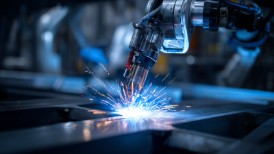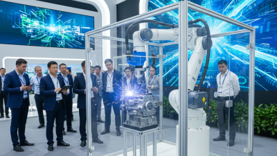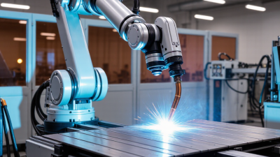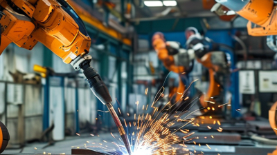
Arc welding is a demanding test of automation. A robot must keep the torch steady, follow the joint, and deliver repeatable welds despite heat, spatter, and changing part fit. Robotic arc welding systems combine the robot with a power source, wire feeder, torch, controls, and safety equipment. The details matter. A small torch-angle error can affect penetration; a poorly positioned fixture can turn a stable cycle into rework.
The market is expanding, but broad automation figures need careful interpretation. The International Federation of Robotics reported 541,302 industrial robots installed worldwide in 2023, with about 4.28 million operating in factories, in World Robotics 2024. These figures cover industrial robots across applications, not arc-welding cells alone. That distinction matters. They show the scale of factory automation, but they do not prove that one welding system is best.
This guide compares ten leading robotic arc welding systems through practical criteria: reach, payload, welding-process compatibility, programming tools, seam tracking, integration, and service support. A compact cell may suit a small fabrication shop, while a high-throughput line needs dependable uptime and fast changeovers. Fit matters more. Buyers should also examine sample welds, consumable costs, operator training, and how the supplier handles maintenance. No ranking replaces a process trial. The right system is the one that produces consistent welds on your parts, within your production constraints.
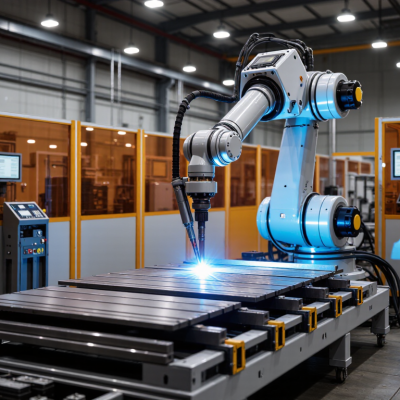
Robotic arc welding systems combine a programmable arm, welding power source, wire feeder, torch, and safety enclosure. The controller moves the torch along a programmed path while the power source creates an electric arc. That arc melts the wire and edges of the metal, forming a joint as the weld cools. Shielding gas helps protect the molten pool from contamination. Sensors can detect changes in seam position or joint fit, though they cannot correct every setup problem.
Tips: Keep the workpiece clean and firmly clamped. Check wire feed, torch angle, and gas flow before production. A small fixture shift can change the weld path. Small shifts count.
In practice, an operator loads parts into a fixture and starts the approved program. The robot follows set travel speed, torch angle, and arc settings. Monitoring tools may flag irregular current, voltage, or seam tracking, giving staff a chance to inspect the weld. Results still depend on material thickness, joint design, and consistent part placement. A program that works well on one batch may need adjustment for another. It is easy to trust automation too much; periodic checks and sample weld inspections remain useful. The best system is not always the fastest one. It should match the part, production volume, and required weld quality.
A robotic arc welding system combines a robot arm, controller, welding power source, torch, and wire feeder. The arm follows a programmed path, while the controller coordinates travel speed, torch angle, and weld timing. The power source sets current and voltage to suit the joint and material. Small details matter.
A stable fixture holds parts in position, and sensors can help detect seams or adjust for small variations. An enclosure and interlocks reduce exposure to the arc, sparks, and moving equipment. In real workshops, fit-up is rarely perfect; even a slight gap can affect bead shape and penetration.
The welding process depends on the part, production rate, and required finish. Gas metal arc welding feeds wire continuously and suits many repeatable production jobs. Flux-cored arc welding can provide higher deposition, though smoke and cleanup may need attention. Gas tungsten arc welding offers precise control on thinner materials, but it is usually slower. Not always simple. Shielding gas, wire type, and travel speed must work together. A practical system review should include sample welds, maintenance access, and operator training, not just robot reach.
A useful comparison begins with the workpiece, not the robot’s headline speed. Record part dimensions, joint locations, material thickness, and the positions required for each weld. Then check whether the arm can reach every seam without awkward torch angles or frequent repositioning. Fit matters. A system that reaches the joint but blocks access for fixtures may slow the whole cell.
Next, assess welding performance using representative parts. Compare travel speed, arc stability, spatter, and weld consistency across repeated runs. Ask how the system handles seam variation, starts, stops, and changes in wire or material. Test the proposed torch, feeder, and power source together. A short demonstration can look convincing; a full shift reveals more. Track cycle time and unplanned stops, not just the fastest pass.
Programming and support deserve equal attention. Operators should be able to adjust paths and recover from common faults without lengthy delays. Review safety equipment, fume extraction, maintenance access, and spare-part availability. These details are easy to underweight during a purchase. I would also question any scorecard that treats every criterion equally: a high payload means little if the torch cannot reach a tight corner. The weighting should reflect actual parts, staffing, and production goals, and it may need revision after trials.
A practical evaluation framework for comparing systems. Scores show suggested assessment priority on a 1–5 scale; they are not measured ratings of specific products.
Compare systems against your application, including weld quality, process capability, throughput, integration, safety, and lifecycle requirements. Validate performance using representative parts and weld procedures.
Ten leading robotic arc welding systems are best understood as configurations, not a universal ranking. A compact enclosed cell suits short, repeatable parts and limited floor space. A floor-mounted six-axis system reaches varied joints on medium-sized assemblies. A collaborative welding cell can support lower-volume work, though guarding and risk assessment still matter. A gantry-mounted system handles long structures with straight, predictable seams. A track-mounted robot extends reach along large frames. Small details matter: torch angle, cable routing, and fixture access.
An integrated positioner rotates the workpiece for improved access to multiple sides. A tandem-robot cell coordinates two torches on suitable high-deposition welds. A multi-robot cell can handle separate joints, but timing and fixture design become more demanding. An offline-programmed system lets teams prepare paths before production; the simulation still needs shop-floor checks. An adaptive system uses seam sensing to adjust for fit-up variation. Not always. Sensors cannot correct every poor joint. Compare these options by material, part size, batch volume, access, and operator skill. A polished demonstration can mislead; real trials should use representative parts and record weld quality, changeover time, and downtime.
| Rank | System Type | Typical Configuration | Typical Reach | Common Welding Processes | Best-Fit Applications | Key Consideration |
|---|---|---|---|---|---|---|
| 1 | Standard Six-Axis Robotic Welding Cell | One articulated robot, welding power source, torch package, safety enclosure, and workholding fixture | Approximately 1.4–2.0 m | GMAW/MIG, pulsed GMAW, FCAW | Repeatable production of frames, brackets, and fabricated assemblies | A strong general-purpose option; fixture access and torch angle must be checked for every joint. |
| 2 | Dual-Station Robotic Welding Cell | One robot serving two fixture stations, often with a rotary index table or shuttle arrangement | Typically 1.4–2.0 m | GMAW/MIG, pulsed GMAW, FCAW | Parts that can be loaded at one station while the robot welds at the other | Can reduce non-welding time, provided station changeover and operator access are well planned. |
| 3 | Robot on a Linear Travel Track | Six-axis robot mounted on a powered floor track, with one or more workstations | Robot reach commonly 1.4–2.0 m; track extends the working envelope | GMAW/MIG, FCAW, and some GTAW/TIG applications | Long weldments, large frames, and multiple fixtures arranged along a production line | Track length, cable management, and coordinated robot motion add planning and maintenance needs. |
| 4 | Long-Reach Robotic Welding System | Long-arm articulated robot with a floor, wall, or elevated mounting arrangement | Often about 2.0–3.0 m, depending on the robot and mounting | GMAW/MIG, FCAW | Large components and welds that are difficult to reach with a standard-arm robot | Long reach does not guarantee good torch orientation; collision and stiffness checks remain important. |
| 5 | Hollow-Wrist Robotic Welding System | Welding robot with torch cables routed through the arm or wrist, paired with a welding package | Commonly about 1.4–2.0 m | GMAW/MIG, pulsed GMAW, FCAW | High-duty-cycle production with frequent wrist movement and tight fixture access | Integrated cable routing can reduce external cable interference; torch-service access still matters. |
| 6 | Robotic Tandem or Twin-Wire GMAW System | Robot and specialized welding equipment feeding two wires or using a tandem arc process | Typically about 1.4–2.0 m | Tandem GMAW and other qualified high-deposition GMAW variants | Thick-section or long-seam work where higher deposition rates can be useful | Requires compatible joint preparation, process development, and control of heat input and distortion. |
| 7 | Robotic GTAW/TIG Welding System | Robot, GTAW power source, torch, and application-specific wire-feeding equipment where required | Often about 1.2–1.8 m | GTAW/TIG, including cold-wire or hot-wire variants when configured | Thin materials, precision joints, and applications requiring controlled weld appearance | Travel speed is generally lower than GMAW; joint fit-up and consistent part presentation are critical. |
| 8 | Robotic Laser-Arc Hybrid Welding System | Robot carrying a combined laser and arc welding head with a laser source and process controls | Commonly about 1.4–2.0 m | Laser-arc hybrid welding | Selected sheet, plate, and structural applications needing deep penetration or high travel speed | Requires laser safety measures, precise joint positioning, and application-specific process qualification. |
| 9 | Vision-Guided Robotic Welding System | Robot with a seam-finding or tracking sensor, welding equipment, and programmed path correction | Typically about 1.4–2.0 m | Usually GMAW/MIG or FCAW; compatible processes depend on the sensing package | Parts with manageable variation in joint location or assemblies that benefit from automatic seam tracking | Sensing can compensate for some variation but does not replace sound fixturing or suitable joint design. |
| 10 | Collaborative Robotic Arc Welding Cell | Collaborative robot, welding package, guarded or monitored work area, and simplified fixture setup | Often about 0.9–1.3 m | Primarily GMAW/MIG, subject to the selected robot and welding package | Small batches, job shops, and tasks where quick reprogramming is valuable | Collaborative operation requires a documented risk assessment; welding hazards may still require physical guarding. |
What Are the Top 10 Robotic Arc Welding Systems?
Matching System Capabilities to Production Needs
The “top ten” is not a universal ranking; the right system depends on the work. Options include compact collaborative cells, fixed-base robots, rail-mounted systems, gantry setups, and cells with positioners or dual stations. Compare each against part size, weld length, production volume, and available floor space. A robot with a wide reach may help with long assemblies, but it can be excessive for small, repetitive parts. Check torch access, cable routing, and fixture clearance using actual workpieces, not only drawings.
Tips: Measure the real part. Test the hardest joint. Record changeover time.
For high-mix work, prioritize quick fixture changes and straightforward programming. Long production runs may benefit more from automated loading, stable fixtures, and a second station that keeps the robot welding during part changes. Confirm the system’s duty cycle, payload, and positioning accuracy against the planned process. Ask how maintenance access works around the torch, cables, and safety equipment. A cell can look efficient on paper and still bottleneck at loading. One awkward joint may also need a different fixture than expected. Test representative parts before settling on a configuration.