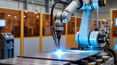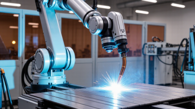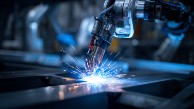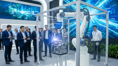
Choosing a robotic arc welding system starts with the weld, not the robot. Joint geometry, material, thickness, production volume, and required quality all shape the right solution. A system that performs well on a flat steel bracket may struggle with a short, restricted fillet weld. Small details matter.
Automation is growing across manufacturing. The International Federation of Robotics reported 541,000 industrial robots installed worldwide in 2023, bringing the operating stock to 4.28 million. These figures cover all industrial uses, not welding alone. Still, they show why manufacturers are evaluating robotic welding for repeatable, high-volume work. IFR President Marina Bill said, “The new World Robotics report shows that the automation trend is accelerating around the world.” That trend does not make every cell a good investment.
For robotic arc welding, compare more than reach and payload. Check torch access, seam tracking, fixture design, power-source compatibility, and programming options. Ask vendors to demonstrate your actual parts, including awkward starts and tight corners. Watch the arc. Inspect the finished bead. Then review changeover time, maintenance needs, operator training, and safety integration. A fast robot can still lose hours to poor fixturing. A polished demo can hide that.
This guide explains how to match a system to your process, production goals, and shop-floor constraints. It also highlights trade-offs that deserve a second look. No system is perfect. The best choice is the one that delivers consistent welds under real working conditions.
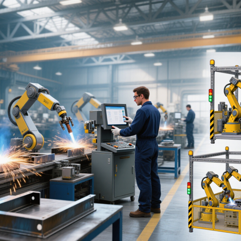
Define the job before comparing robotic arc welding systems. Record annual volume, batch size, shift pattern, and target cycle time. Measure the actual parts, including material grade, thickness, joint type, and weld length. A 6-millimeter fillet weld on a repeatable bracket is a different task from a long seam on a large, awkward frame.
Set measurable welding objectives: acceptable defect rate, bead appearance, changeover time, and required production uptime. Note fixture access and how much part variation operators see. The International Federation of Robotics’ World Robotics 2024 report counted 4,281,585 industrial robots operating worldwide at the end of 2023. That figure shows broad adoption, not that automation suits every weld cell. The American Welding Society has estimated that 330,000 welding professionals will be needed in the United States by 2028; this workforce outlook can inform staffing plans, but it does not replace a production study. Walk the line with operators. Watch a real changeover. A spreadsheet can miss spatter cleanup, cable reach, or parts that arrive slightly warped. That matters. Capture these exceptions, then test the proposed cycle and weld quality on representative parts before setting performance targets.
Choosing a robotic arc welding system starts with the material and joint, not the robot alone. Mild steel, stainless steel, and aluminum respond differently to heat, wire choice, and shielding gas. For many steel parts, GMAW offers productive, steady welds. Aluminum may need controlled wire feeding and careful heat management. Thin sheet can warp if heat input is excessive. Small details matter.
Joint design narrows the options. A lap joint may tolerate minor fit-up variation, while a tight butt joint needs consistent edges and accurate torch positioning. Deep grooves can require multiple passes or a process suited to higher deposition. A clean sample joint can be misleading; production parts rarely stay perfectly aligned.
Tips: Test the actual material thickness and joint geometry. Check root access, gap variation, and welding position. Record wire, gas, travel speed, and voltage during trials. Keep a few imperfect parts in the evaluation; they reveal where the setup may struggle. Seam tracking can help, but it cannot fix poor fixturing or an unsuitable joint. Read the weld cross-section and inspect for porosity, lack of fusion, and distortion before committing to a cycle time.
A robotic arc welding cell should be configured around the joint, not the robot’s headline reach. Map each weld’s length, torch angle, approach path, and likely obstruction before selecting the arm. A six-axis robot may reach the part, yet still struggle to hold a stable torch angle near a flange. Check payload with the torch, cables, and sensors installed. Then verify reach at the positioner’s full rotation, not only in the starting pose. Small details matter.
Choose a positioner that presents the joint consistently and supports the fixture, part, and clamping loads. A two-axis unit can improve access, but it also adds coordination and maintenance demands. Keep the workcell compact without crowding the operator’s loading area, guarding, or service access. The International Federation of Robotics reported 541,302 industrial robot installations worldwide in 2023; this broad figure signals adoption, not welding-specific demand (World Robotics 2024). The American Welding Society has projected demand for 330,000 welding professionals by 2028, making repeatable automation relevant, but not a substitute for sound process design (AWS workforce outlook). A tidy CAD layout can still mislead. Recheck cable routing, fume extraction, and fixture access with the actual part. I would also leave room for a future fixture change; teams often underestimate that need.
Compare common cell configurations against key planning considerations. Scores are illustrative priorities on a 1–5 scale, not measured performance results.
A fixed fixture can suit stable parts with accessible joints. A single-axis positioner can rotate parts for improved weld access, while a multi-axis positioner can support more complex part orientations. Confirm robot reach and payload, positioner capacity, torch access, cycle time, and workcell safety against your actual parts and production requirements.
A robotic arc welding cell should be judged by how safely people can work around it, not just by its rated speed. Check the guarding, interlocked access points, emergency stops, and safe recovery steps. Can an operator clear a fault without reaching into the robot’s working area? That question matters. Also consider fume extraction, cable routing, and torch collision detection; these details affect daily work. A safety review should reflect the actual cell layout and tasks, not only a drawing.
Controls should make welding jobs repeatable and faults understandable. Look for clear weld schedules, controlled access to parameter changes, and messages that tell technicians what failed. Test recovery after a wire-feed fault or interrupted cycle. Test it cold. System integration deserves equal attention: confirm that fixtures locate parts consistently, sensors detect loading errors, and the robot exchanges reliable signals with the positioner and production line. Check how recipe changes move between the cell and the wider process. A simulation can look tidy, yet real parts arrive with variation, spatter builds up, and changeovers take longer than expected. I would leave time for operator trials; they often expose awkward reach or confusing screens that a design review misses.
| Evaluation Area | What to Assess | Questions and Evidence to Request | Practical Acceptance Check |
|---|---|---|---|
| Application and Part Fit | Part dimensions, joint locations, material, thickness, weld positions, and variation between parts. | Can the proposed process reach every required joint without collisions? Are actual production parts and fixtures included in the demonstration? | Run representative parts, including the most difficult joint positions and normal dimensional variation. |
| Robot Reach and Payload | Working envelope, torch orientation, wrist limits, torch and cable weight, and clearance around fixtures. | Request reach and payload information for the proposed configuration. Check whether the torch, cables, sensors, and accessories are included in the payload assessment. | Confirm the robot can reach all welds with suitable torch angles while avoiding singularities, fixtures, and nearby equipment. |
| Weld Quality and Process | Welding process, consumables, joint preparation, position, travel speed, and required weld acceptance criteria. | Are sample welds produced using the intended materials and joint designs? How are weld schedules and process parameters selected and controlled? | Inspect trial welds against the applicable drawing, procedure, and quality requirements; document the test conditions and results. |
| Cycle Time and Throughput | Arc-on time, robot travel, part loading, clamping, inspection, changeover, and expected production availability. | Is the quoted cycle time based on a complete production sequence or only welding time? Are loading, repositioning, and routine interruptions included? | Time repeated cycles with representative parts, operators, fixtures, and production steps; compare results with the required takt time. |
| Risk Assessment | Robot motion, welding arc radiation, hot workpieces, sparks, fumes, electrical hazards, and access for setup and maintenance. | Request a documented risk assessment for the complete cell and its intended use. Confirm applicable local regulations and relevant standards, such as ISO 10218 and ISO 13849-1, are considered. | Review hazards and safeguards with qualified safety personnel before installation and before production use. |
| Guarding and Safety Functions | Perimeter guarding, interlocked access doors, emergency stops, safety-rated control functions, and safe maintenance access. | Are protective devices suitable for the assessed risks? Are safety functions validated, and can faults be identified and reset according to the documented procedure? | Verify safeguarding and safety functions through documented commissioning tests. Do not treat a collaborative robot as inherently safe for every application. |
| Fume and Fire Controls | Welding fume capture, ventilation, spark containment, combustible materials, and hot-part handling. | Does the extraction arrangement suit the process and workpiece? Are ventilation needs and fire-prevention measures addressed in the cell design? | Check that extraction is effective at the source and that site-specific fire and ventilation requirements are met. |
| Robot and Welding Controls | Program creation, weld schedule selection, job recall, alarms, controlled restart, and operator access levels. | Can authorized staff edit and back up programs? Are weld parameters, robot motion, and fault messages understandable to the people who will use the cell? | Have operators perform a job change, respond to common faults, and restore a saved program using documented instructions. |
| Sensors and Process Monitoring | Seam finding, part presence, weld monitoring, torch collision detection, and process data capture, where required. | Which sensors are included, and what conditions do they detect? Are sensor limits, failure responses, and data records clearly specified? | Test the system with representative part offsets and defined fault conditions; confirm the response is suitable for the application. |
| Cell and Plant Integration | Fixtures, positioners, material handling, upstream and downstream equipment, plant networks, and production data systems. | Are interface responsibilities, signals, communication methods, and equipment boundaries documented? Are required connections compatible with the plant? | Test the complete sequence, including handshakes, interlocks, part identification, and recovery from interrupted transfers. |
| Changeover and Flexibility | Product mix, fixture changes, program selection, torch access, and future part variants. | How are recipes or programs selected and verified? What hardware or re-teaching is needed when a new part is introduced? | Perform a representative changeover and record the time, tools, training, and adjustments required. |
| Maintenance and Support | Consumable replacement, torch cleaning, calibration, spare parts, diagnostics, and service access. | Are maintenance intervals, recommended spares, manuals, training, and support arrangements provided? | Confirm maintenance tasks can be performed safely and that required consumables and critical spare parts are available. |
| Acceptance and Documentation | Installation checks, safety validation, process trials, operator training, and handover records. | Are acceptance criteria defined in advance? Will the supplier provide drawings, electrical documentation, risk-assessment records, and backup files? | Use a written acceptance checklist covering safety, weld quality, cycle time, interfaces, training, and documentation. |
Selection note: Confirm applicable standards, regulations, and acceptance criteria for the installation location and application. Final safety decisions should be based on a site-specific risk assessment and validation by qualified personnel.
A robotic arc welding system costs more than its purchase price. Include the robot, power source, torch, fixtures, safety equipment, fume extraction, programming, and installation. Add training, replacement parts, routine maintenance, and planned downtime. These costs can change the payback period considerably.
Numbers can mislead. Compare suppliers using the same production assumptions: parts per shift, changeover frequency, labor coverage, and expected service life. Ask for a written estimate of integration work and recurring consumables. A low initial quote may leave important tasks outside its scope. Your own cost model will still contain estimates; mark them clearly and revisit them after a pilot run.
Validate performance with your actual parts, not only a polished demonstration piece. Test different joint positions, material thicknesses, and normal fixture variation. Watch the arc. Record cycle time, weld inspection results, changeover time, and interruptions across repeated runs. Test the cell. Include the operators who will load parts and respond to faults. A single successful weld proves little, and a short trial may miss awkward recovery steps. Note where the system needs adjustment, even if that makes the first comparison less flattering.