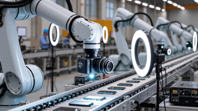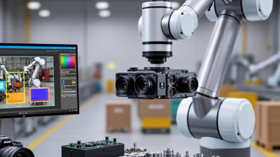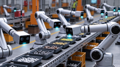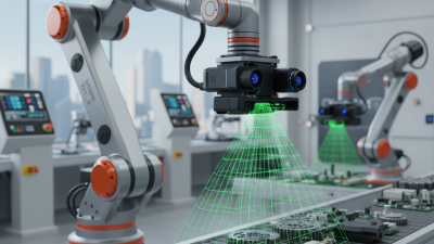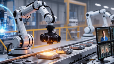
A 3D vision system helps a robot perceive depth, shape, and position in its workspace. Unlike a standard camera, it can estimate how far objects are from the sensor. This added information supports tasks such as locating a part on a moving conveyor or guiding a gripper toward a box. The details matter: a few millimeters of error can affect a tight pick, while poor lighting or reflective surfaces can confuse even capable equipment.
The term 3d vision systems for robots covers several approaches, including stereo cameras, structured light, and time-of-flight sensors. Each captures depth differently, so the right choice depends on the task, working distance, speed, and environment. Software then processes sensor data, often as a depth map or point cloud, and identifies useful features for the robot’s controller. In a practical setup, an engineer may check camera placement, calibrate the sensor against the robot, and test how readings change when an object shifts.
It is not magic. A system may struggle with occlusion, transparent materials, dust, or changing light. Testing with real parts is essential, and results should be checked against the required accuracy and cycle time. Even a well-calibrated setup can need adjustment after a camera moves. That limitation deserves attention. Understanding both the capabilities and the failure points makes it easier to judge whether 3D vision is suitable for a specific robotic application.
What Is a 3D Vision System for Robots?
Definition and Purpose of a 3D Vision System for Robots
A 3D vision system helps a robot interpret the shape and position of objects in its workspace. It gathers depth information, often alongside ordinary image data, to build a spatial picture. Depth matters. A flat image may show a cup, but depth can help estimate how far away it is and where its rim sits. The robot uses this information to guide actions such as locating parts, avoiding obstacles, or aligning a gripper.
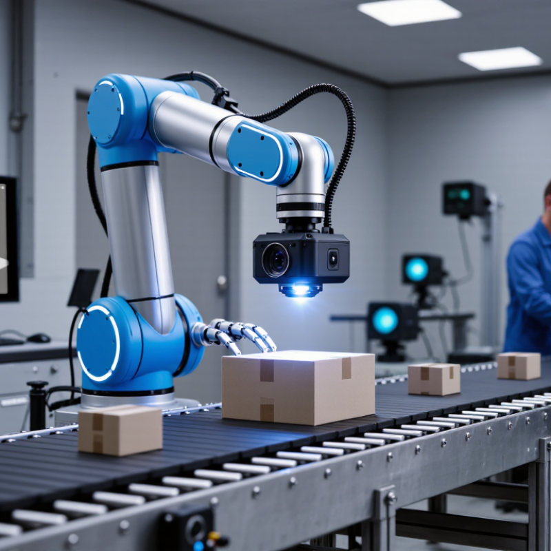
The system typically includes a camera or depth sensor, processing software, and a connection to the robot’s control system. Together, these components turn measurements into useful coordinates. For example, on a packing line, the system might locate a box and estimate its orientation before the robot reaches for it. Results depend on lighting, surface texture, and calibration. A shiny object can confuse depth readings. Real setups are rarely perfect, and that is worth planning for.
Tips: Test with the actual objects and lighting used at work. Check calibration regularly, and leave room for measurement error. A system can guide a robot, but it does not make every decision reliable.
A 3D vision system captures depth information to estimate an object's position in three-dimensional space. These illustrative measurements show how detected objects at different distances could be represented for robotic tasks such as locating and picking items. Actual results depend on the sensor, environment, and setup.
What Is a 3D Vision System for Robots?
Core Sensors and Components
A 3D vision system combines depth sensors, image processing, and robot-position data to locate objects in space. Its camera may use stereo imaging, structured light, or time-of-flight sensing. Stereo cameras estimate depth by comparing two views, while time-of-flight sensors measure returned light. Each method behaves differently around shiny, dark, or transparent surfaces. Depth is not truth.
A complete setup also needs controlled illumination, a rigid camera mount, calibration targets, and a processor. Calibration maps camera coordinates to the robot’s working frame, so a detected point can become a usable movement target. In practical installations, even a slightly loose bracket can shift picks. Lighting changes can also add noise. Calibration matters.
The need for reliable perception is growing alongside robot use. The International Federation of Robotics reported 4,281,585 industrial robots operating worldwide in 2023, with 541,302 new installations that year in World Robotics 2024. These figures describe robot deployment, not vision-system sales, but they show why dependable sensing matters. Teams should match sensor type to object size, working distance, cycle time, and surface finish. A fast sensor may still miss a clear plastic edge. Testing with real parts remains essential.
A 3D vision system helps a robot estimate where surfaces sit in space, not just how they look. A stereo camera compares two views; a depth camera or lidar can measure distance directly. The sensor records points with positions, forming a point cloud around the robot. Edges, floor planes, and object shapes become useful clues. Depth is imperfect.
Software transforms measurements into a shared coordinate frame, so points remain meaningful as the robot moves. It may combine successive scans with wheel motion or inertial data to build a local map. For example, a mobile platform can locate a chair leg, track a doorway, and leave clearance before turning. The map updates continuously, but moving people and objects can make earlier geometry misleading. Lighting, reflective surfaces, thin cables, and occlusion may create gaps or false depth.
A reliable system checks measurements against nearby points and earlier observations. Calibration matters: a small camera tilt can shift estimated edges and narrow a robot’s safe path. Engineers test across varied floors, distances, and motion speeds, then inspect where the map disagrees with reality. No map is complete. Uncertainty matters. When depth estimates conflict, a robot can slow down, gather another view, or choose a wider route. Some reflections remain difficult to interpret.
What Is a 3D Vision System for Robots?
Methods for Processing and Interpreting 3D Data
A robot’s 3D vision system converts sensor readings into a model of nearby surfaces and objects. A depth camera may report the distance to thousands of points in each frame. Together, these points form a point cloud. Noise is unavoidable. Reflections, dark materials, and motion can leave gaps or stray points. Filtering reduces some errors, but aggressive filtering can erase thin edges that matter for grasping.
Processing often begins by transforming measurements into the robot’s coordinate frame. This step lets the system compare an object’s position with the arm, gripper, or work surface. Calibration errors show up as small but persistent offsets. A cup may appear centered on screen yet sit several centimeters from its measured location. That matters. Segmentation then separates useful regions, such as a box from the table beneath it. Systems may use geometric rules, learned models, or both.
To interpret the scene, software can estimate planes, edges, surface normals, and object poses. A robot may use these features to choose a grasp point with enough clearance for its fingers. Confidence scores help flag uncertain measurements, rather than treating every point as fact. In practice, changing light or a transparent surface can still confuse the model. A sensible system checks new frames and updates its estimate, though that adds processing time. Speed is not the only goal. A slightly slower, well-calibrated interpretation can prevent a poorly aligned movement.
A 3D vision system helps a robot understand an object’s shape and position, not just its outline. In bin picking, a camera can map a crowded container and estimate which part is reachable. The robot then adjusts its gripper instead of repeating one fixed motion. Small parts matter. A few millimeters can decide whether a grasp succeeds.
On an assembly line, depth data can guide a robot to align a peg with a hole or place a component at a measured height. Inspection tasks use the same information to spot dents, missing pieces, or uneven surfaces. In mobile robotics, 3D sensing can reveal a pallet, a step, or a person near the planned route. The useful result is not a pretty image. It is a reliable position estimate the robot can act on.
Real workspaces are less tidy than demonstrations. Shiny metal, dark surfaces, dust, and overlapping objects can distort depth readings. Depth can mislead. Calibration and lighting checks help, but they do not remove every uncertainty. A practical setup should test the actual parts, motion speed, and surroundings before production. When the robot hesitates or chooses a poor grasp, that is useful evidence: the sensing, planning, or task design may need another look.
| Robotic Task | How 3D Vision Is Used | Robot Action | Typical 3D Output | Practical Consideration |
|---|---|---|---|---|
| Random bin picking | Measures the position and orientation of parts scattered in a container and identifies accessible grasp points. | Selects a part, approaches it, grasps it, and transfers it to a destination. | Depth image or point cloud, object pose, and candidate grasp locations. | Parts may overlap or hide one another; reflective surfaces and tight packing can make detection and grasp planning harder. |
| Machine tending | Locates workpieces and checks their pose relative to a machine fixture or loading area. | Picks up a workpiece, aligns it with the machine, and loads or unloads it. | Workpiece position and orientation relative to the robot or fixture. | Reliable calibration between the camera, robot, and machine is important for accurate placement. |
| Depalletizing | Maps carton or item surfaces and estimates the position of the next reachable load in a stack. | Removes items layer by layer and places them onto a conveyor or staging area. | 3D surface map, item boundaries, and pick locations. | Changing stack heights, occlusion, damaged packaging, and unstable loads can affect detection and handling. |
| Part assembly | Finds component features and checks their alignment before parts are joined. | Positions, inserts, or mates components according to the assembly sequence. | Component pose, feature locations, and alignment offsets. | Small clearances may require careful calibration and additional force or tactile feedback during insertion. |
| Bin and tote picking | Distinguishes items in a container and estimates which items are visible and reachable. | Grasps selected items and transfers them to an order, conveyor, or work area. | Object locations, surface geometry, and possible grasp regions. | Similar-looking objects, transparent packaging, and heavy occlusion can make item identification difficult. |
| 3D inspection and measurement | Compares a scanned surface or measured features with expected geometry or tolerances. | Moves a sensor or part through an inspection path and flags detected deviations. | Point cloud, surface profile, dimensions, or deviation map. | Measurement results depend on sensor resolution, viewing angle, surface finish, and the inspection setup. |
| Welding and surface processing | Locates seams, edges, or workpiece surfaces to help define a tool path. | Guides a welding, cutting, or finishing tool along a detected path. | Surface geometry, seam location, and path reference points. | Sensor protection, line-of-sight, changing surface conditions, and process heat or debris must be considered. |
| Robot navigation and obstacle avoidance | Builds a local representation of nearby surfaces and obstacles from depth measurements. | Plans or adjusts motion to move through an environment while avoiding detected obstacles. | Depth map, local point cloud, or 3D occupancy representation. | Performance depends on field of view, lighting conditions, sensor range, and how quickly the scene changes. |
A 3D vision system provides spatial information—such as depth, surface shape, position, or orientation—that helps a robot perceive objects and plan actions. The specific output and achievable performance depend on the sensor, software, calibration, and operating environment.